
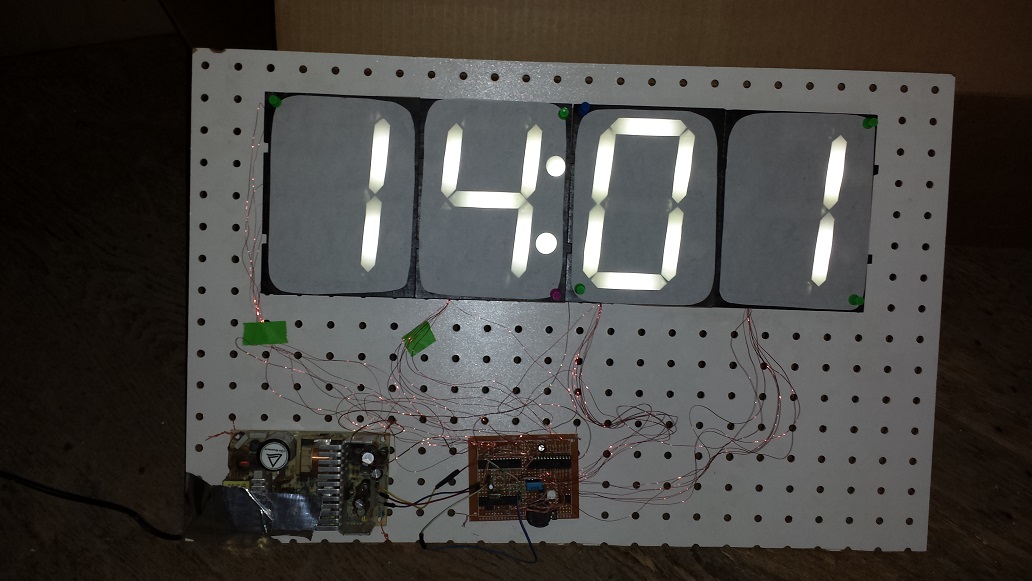

One of the first things I noticed after joining Make Lehigh Valley was that there was no easy way to tell what time it was if you weren’t near a computer. After discovering a box of LEDs that had been recently donated to the space, I decided I would fix that problem. The LED clock itself is made of mostly recycled and donated parts. The 7-segment displays are made from laser-cut cardboard and tissue paper as the diffuser. The LEDs were rather unusual in that they were arrays of dies in a rectangular metal package; this lent itself well for the 7-segment arrangement.

The control board is about as simple as it gets. The Atmega328 communicates to two MCP23016 16 bit I/O expanders and a Dallas DS1307 real-time clock chip via I2C. Also onboard is a DHT11 temperature and humidity sensor. This allows the clock to function like one you would see at a bank. The display cycles through time, temperature and humidity – three seconds each.

Since the LEDs are actually small arrays, they have a forward voltage of about 7v – I was thinking I would need to multiplex the display and use additional transistors to handle the voltage, but the LEDs were plenty bright enough at 50mA (the output rating of the IO pins on the expander IC) so I was able to use a dual rail power supply to power the LEDs with the IO expander directly (well, with current limiting resistors anyway). The LEDs are connected in a common anode arrangement to the +12v rail of a power supply scavenged from a 10mbps ethernet hub. The logic runs from the 5v rail. When the pins on the IO expander go high (+5v), there is only 5vdc across the LED and so it stays dark. When the pin goes low, it gets the full 12v through 220 ohm resistors, limiting the current to about 22mA.